|
Building an emulator is an endless project. There is always work to do with code optimization, modernization, accuracy, features, debugging etc. My focus has largely been on accuracy because it presents interesting - and admittedly sometimes frustrating - challenges. But I also want my emulator to have useful features. Being able to playback RZX files (recordings of ZX Spectrum sessions, mostly used for game walkthroughs) is a nice feature, and the ideas behind the file format are interesting, so I decided to try implementing it. Principles During RZX playback, the RZX file supplies the emulator with IN-port values and information about when to start a new frame and when to trigger interrupts. The emulator doing the playback therefore only needs to emulate the Z80 accurately (or at least in the same way as the recording emulator) and handle display and sound. Timing is not an issue since it will be fully controlled by the RZX playback process. And external hardware doesn't have to be emulated since all IN-port data is provided in the file. File Format An RZX file consists of several blocks of data including a snapshot with the initial state of the machine and a recording block with information about IN-port data and frame lengths (measured by the number of instruction fetches per frame). The snapshot and recording blocks can optionally be compressed. It seems that the snapshot can be in any format, but I have only found examples with Z80 and SZX snapshots. Additionally, there are blocks with information about the RZX revision and the file origin. An optional security block is used to ensure that the file hasn’t been tampered with. Considerations It is important to understand that a frame in an RZX file does not always correspond to a display frame in the emulator (which is controlled by the imagined video signal). This is because the RZX format specifies that there can only be one interrupt during a RZX frame. So, if interrupt is retriggered during a display frame, this frame will correspond to two RZX frames. Another thing to note is that interrupts can only be triggered if IFF1 was already enabled before the first instruction in the RZX frame, and then it will be triggered first thing. So if IFF1 was disabled and the first instruction of the frame is EI, there will be no interrupt during the frame. During testing I noticed that when playing back the WEC Le Mans recording in the RZX Archive, the program got stuck at the HALT instruction at address $8192 during frame 20854. This was because the previous frame ended with an EI instruction at $8191. The emulator then applied the rule that an interrupt can’t be triggered directly after EI, which led to a delayed interrupt. This rule must therefore be ignored during RZX playback so that an interrupt is always triggered first thing in a new frame (provided that interrupt is enabled). Finally, note that when counting instruction fetches until it is time to start a new frame, prefixed instructions must be allowed to be completed before ending the frame, even if it means that the number fetches in the frame is exceeded. This should be obvious but I missed it at first. Implementation in SoftSpectrum 48 To implement RZX playback functionality i added the RZXFile class, which interprets and stores the RZX file data in arrays for easy access. During playback this class provides IN-port data to the Z80 class and publishes events for the playback status (used to update the GUI and to control the emulator behavior) During playback, the TStateCounter class is relieved of its responsibility for deciding when a frame should end. This is instead handled by the Controller class, which counts the number of instruction fetches during each frame, and - when the maximum number for the frame has been reached - triggers a new RZX frame, initiates an interrupt window (provided IFF1 is true) and a new display frame (except when interrupt is retriggered). The Z80 class is only affected in that it gets its IN-port data from the RZXfile class during playback. Also, it updates an instruction fetch counter each time the R-register is updated during the instruction fetch process. The MainWindow class displays playback information (current and total frames) from the RZXFile. I have implemented support for RZX revision 0.12 and 0.13 excluding security information blocks. Only Z80 and SZX snapshots are supported. The specification also allows for external snapshots, but I haven't implemented support for this. I have tested quite a few RZX files and I think that everything works as it should (with the limitations mentioned above). If not, I would be glad to learn of any RZX file that isn't handled correctly. Links A specification for the RZX format can be found here: WWR - RZX technical specifications (worldofspectrum.net).
RZX recordings can be found in the RZX Archive.
0 Comments
As a user it doesn't really matter to me if loading a tape takes 2 seconds or 5 seconds - either way it is nothing compared to the loading times back in the day. Still, I always want to improve my emulator if I can, and tape flash loading has not been as fast as it apparently can be, when you compare it to other emulators. Also, as in the case of the Bad Apple 2 demo, some tape files won't even load correctly without efficient flash loading. So I decided to have one more look at the flash loading routines and found that I had made things much more complicated than I had to, and that a simpler solution was much faster!
Previously, the emulator used the header information to flash load the following data block, but the header itself was never flash loaded. If speed load and edge detection is activated, loading a header is fast anyway, but there is still a noticeable delay. Also, this method required separate routines for loading program blocks, data blocks and headerless blocks. After analyzing the ROM routines (using this excellent site) and doing some experimenting I found that by intercepting the LD BYTES ROM routine the emulator could flash load every tape block, regardless of type, so everything could be handled by the same routine - and much faster.
Below is the new flash loading routine in a static class, which is called by the Controller class after each instruction, when tape loading is active. The actual flash load routine is very simple, and the bulk of the code is needed to handle different errors that can occur. In short, the process consists of the following steps:
namespace SP48
{
    /// <summary>
    /// Loads tape data directly into RAM, bypassing the ROM loading routines.
    /// </summary>
    public static class TapeFlashLoader
    {
        /// <summary>
        /// Checks if the program counter is at an entry point in the ROM tape loading routines
        /// and attempts to flash load the next tape block.
        /// </summary>
        /// <returns>
        /// An integer representing the index of the <see cref="TapeBlock"/> that was flash loaded. A return
        /// value of -1 means that flash loading could not be performed.
        /// </returns>
        public static int FlashLoad(Z80 z80, Memory memory, TapeManager tapeManager)
        {
            // The return value, representing the index of the TapeBlock which was flash loaded.
            int lastBlockIndex = -1;

            // The LD BYTES ROM routine is intercepted at an early stage just before the edge detection is started.
            // Check that the tape position is at the end of a block and that there is a following block to flash load.
            if (z80.PC == 0x056A && tapeManager.NextBlock != null && tapeManager.CurrentTapePosition > tapeManager.NextBlock.StartPosition - 10)
            {
                // The target address for the data is stored in IX.
                int dataTargetParameter = 256 * z80.I1 + z80.X;

                // The block length (number of bytes) is stored in DE.
                int dataLengthParameter = 256 * z80.D + z80.E;

                // The flag byte is stored in A'.
                int flagByte = z80.APrime;

                // Check for various errors:
                // Is there a mismatch between the block type and the flag byte in the A' register?
                if (tapeManager.NextBlock.BlockTypeNum != flagByte && dataLengthParameter > 0)
                {
                    // Don't load the block, but reset all flags.
                    z80.CarryFlag = 0;
                    z80.SignFlag = 0;
                    z80.ZeroFlag = 0;
                    z80.HalfCarryFlag = 0;
                    z80.Parity_OverflowFlag = 0;
                    z80.SubstractFlag = 0;
                    z80.F3Flag = 0;
                    z80.F5Flag = 0;

                    // The A register is updated by XOR:ing the flag byte with the block byte read from the file.
                    z80.A = flagByte ^ tapeManager.NextBlock.BlockTypeNum;
                }
                else

                // Is the expected number of bytes larger than the actual length of the block?
                if (dataLengthParameter > tapeManager.NextBlock.BlockContent.Length)
                {
                    // If the DE register indicates a too long data length, the loader will fail after
                    // loading the block and it expects one more byte.
                    memory.WriteDataBlock(tapeManager.NextBlock.BlockContent, dataTargetParameter);

                    // When a new edge is not found, flags carry = 0 and zero = 1.
                    z80.CarryFlag = 0;
                    z80.ZeroFlag = 1;

                    // The other flags are set by the last INC B (from 0xFF) at 0x05ED.
                    z80.HalfCarryFlag = 1;
                    z80.SignFlag = 0;
                    z80.Parity_OverflowFlag = 0;
                    z80.SubstractFlag = 0;
                    z80.F3Flag = 0;
                    z80.F5Flag = 0;

                    // Check that we're not dealing with a data fragment (in which case IX and DE are intact).
                    if (tapeManager.NextBlock.BlockContent.Length >= 2)
                    {
                        z80.I1 = (dataTargetParameter + tapeManager.NextBlock.BlockContent.Length + 1) / 256;
                        z80.X = (dataTargetParameter + tapeManager.NextBlock.BlockContent.Length + 1) - 256 * z80.I1;
                        z80.D = (dataLengthParameter - (tapeManager.NextBlock.BlockContent.Length + 1)) / 256;
                        z80.E = (dataLengthParameter - (tapeManager.NextBlock.BlockContent.Length + 1)) - 256 * z80.D;
                    }

                    z80.A = 0;
                }
                else
                // Is the expected number of bytes smaller than the length of the block?
                if (dataLengthParameter < tapeManager.NextBlock.BlockContent.Length)
                {
                    memory.WriteDataBlock(tapeManager.NextBlock.BlockContent, dataTargetParameter);

                    // When calculating the checksum for the loaded data, there are two different cases,
                    // either the block length parameter equals zero, in which case there is no parity
                    // calculated and the checksum contains the flag byte.
                    // Otherwise, the checksum is calculated in the usual way but only for the number
                    // of bytes specified in the data length parameter + 1.
                    int calculatedCheckSum;
                    if (dataLengthParameter == 0)
                        calculatedCheckSum = flagByte;
                    else
                    {
                        calculatedCheckSum = flagByte;

                        // The checksum is calculated by XOR:ing each byte of data with the flag byte.
                        for (int i = 0; i < dataLengthParameter + 1; i++)
                            calculatedCheckSum ^= tapeManager.NextBlock.BlockContent[i];
                    }

                    // The flags are set by the CP 0x01 operation at 0x05E0, where A = the current checksum.
                    int flagTest = calculatedCheckSum - 1;
                    z80.CarryFlag = BitOps.GetBit(flagTest, 8);
                    z80.SignFlag = Flags.SignFlag(flagTest);
                    z80.ZeroFlag = Flags.ZeroFlag(flagTest);
                    z80.HalfCarryFlag = Flags.HalfCarryFlagSub8(calculatedCheckSum, 1, z80.CarryFlag);
                    z80.Parity_OverflowFlag = Flags.OverflowFlagSub8(calculatedCheckSum, 1, flagTest);
                    z80.SubstractFlag = 1;
                    z80.F3Flag = 0;
                    z80.F5Flag = 0;

                    // Update the A, IX and DE registers.
                    z80.A = calculatedCheckSum;
                    z80.I1 = (dataTargetParameter + dataLengthParameter) / 256;
                    z80.X = (dataTargetParameter + dataLengthParameter) - 256 * z80.I1;
                    z80.D = 0;
                    z80.E = 0;
                }
                else
                // Is the expected number of bytes equal to zero?
                if (dataLengthParameter == 0)
                {
                    // There is no parity check, so the checksum contains the block type value.
                    int calculatedCheckSum = 0xFF;

                    // The flags are set by the CP 0x01 operation at 0x05E0, where A = the current checksum.
                    int flagTest = calculatedCheckSum - 1;
                    z80.CarryFlag = BitOps.GetBit(flagTest, 8);
                    z80.SignFlag = Flags.SignFlag(flagTest);
                    z80.ZeroFlag = Flags.ZeroFlag(flagTest);
                    z80.HalfCarryFlag = Flags.HalfCarryFlagSub8(calculatedCheckSum, 1, z80.CarryFlag);
                    z80.Parity_OverflowFlag = Flags.OverflowFlagSub8(calculatedCheckSum, 1, flagTest);
                    z80.SubstractFlag = 1;
                    z80.F3Flag = 0;
                    z80.F5Flag = 0;

                    z80.A = calculatedCheckSum;
                }
                else
                // Flash load the block and update IX, DE and AF.
                {
                    int lastBytePos = memory.WriteDataBlock(tapeManager.NextBlock.BlockContent, dataTargetParameter);
                    int calculatedCheckSum = 0;

                    // The flags are set by the CP 0x01 operation at 0x05E0, where A = the current checksum.
                    int flagTest = calculatedCheckSum - 1;
                    z80.CarryFlag = BitOps.GetBit(flagTest, 8);
                    z80.SignFlag = Flags.SignFlag(flagTest);
                    z80.ZeroFlag = Flags.ZeroFlag(flagTest);
                    z80.HalfCarryFlag = Flags.HalfCarryFlagSub8(calculatedCheckSum, 1, z80.CarryFlag);
                    z80.Parity_OverflowFlag = Flags.OverflowFlagSub8(calculatedCheckSum, 1, flagTest);
                    z80.SubstractFlag = 1;
                    z80.F3Flag = 0;
                    z80.F5Flag = 0;

                    z80.A = calculatedCheckSum;

                    // Set IX to the same value as if the block had been loaded by the ROM routine.
                    z80.I1 = lastBytePos / 256;
                    z80.X = lastBytePos - 256 * z80.I1;

                    // Set DE to 0.
                    z80.D = 0;
                    z80.E = 0;
                }

                // Keep track of the index of the last loaded tape block. This information
                // can be used to rewind the tape to the start position of the next block
                // after an auto pause.
                lastBlockIndex = tapeManager.NextBlock.Index;

                // Skip forward to the end of the block which was just flash loaded into RAM.
                tapeManager.GoToEndOfBlock(tapeManager.NextBlock.Index);

                // Skip to the end of the LD BYTES ROM routine (actually a RET, so it doesn't really matter which RET instruction we point to here).
                z80.PC = 0x05E2;
            }

            return lastBlockIndex;
        }
    }
}
I'm sure there is still room for improvement here, but so far flash loading is much faster and more reliable than before!
Since the emulated Z80 runs a lot faster than a real Z80, the instructions for the AY chip will be delivered in short bursts every frame (at 50Hz). Because of this, the generated audio signal will not be timed exactly right. Normally, this won't be a problem, considering that the error will be less than 0.02 seconds. However, when the program uses precise timing to generate digital sound, it will not work.
One way to generate digital sound on an AY chip is to set both the tone and noise signals off in the mix. This will result in a permanent high output, which can then be modulated with the volume control to produce a waveform. This technique is used in this demo: b2gemba.tap. To handle this I implemented a class which worked in the same way as the beeper, using the nAudio BufferedWaveProvider. Activated by setting both tone and noise off in the mix, whenever the volume changed, I would feed the buffer with a number of samples corresponding to the number of T-states that had passed since the previous volume change, and with the previous amplitude. The nAudio player would then play back the samples at the correct rate. This worked in principle, but the sound quality was not great. I also found that some programs use another technique which my solution did not support. One such game is Parsec (an excellent game by the way) which modulates the volume of a high pitch signal (pitch value 0) to generate some speech synthesis. To handle this I had to synchronize the regular AY signal with the Z80. After some failed experimenting with extending the buffered wave provider to handle all aspects of the AY signal I choose instead to implement an instruction queue of sorts in my existing solution. Instead of processing instructions sent to the AY directly, the instructions are now placed in a queue, together with the sample number within the frame where the instruction should be processed (the sample number corresponding to the T-state at which the instruction was received). I then added a routine in the signal generator Read-method to pull instructions from the queue at the correct point in time with regard to the current sample number within the frame being processed. This solution now also handles the case where a constant high signal is modulated. I thought I had all timings reasonably under control, but this was not the case. The 128 KB Spectrum models can switch between the normal screen memory (bank 5) and the shadow screen (bank 7) by writing to port #7FFD. This feature can be seen used in demos like this. I had assumed that the actual bank switch would happen instantaneously after the command was received and the correct amount of T-states had passed, but things turned out to be a bit more complicated. There is a suite of test programs zxtests-3 written by Jan Bobrowski which used to be published at http://wizard.ae.krakow.pl/~jb/qaop/tests.html. This site is not online anymore but it can be accessed on waybackmachine.org. These tests are very useful for testing emulation of various timing aspects and they have also sometimes been adapted by developers to examine specific scenarios. In 2014, Patrik Rak did some modifications to the test suite and added a test ptime which examines what happens when the screen memory is switched at different T-states. This is discussed on the World of Spectrum forum here and here. What the ptime test does is that it triggers a screen bank switch at a specific T-state which can be increased or decreased manually. Before the switch, a black screen in bank 7 is displayed, which then switches to this screen in bank 5: 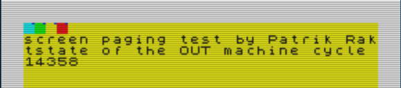 The ptime test. As the T-state at which the switch is triggered is increased, a black line from the shadow screen will appear. This is because the switch occurs after the ULA has already begun drawing the screen from the black shadow screen data. 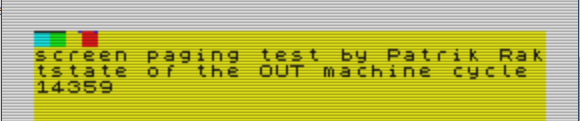 The ptime test with a visible black line. I don't have access to any 128 KB machine, but test results from a Spectrum 128 and a +3 were reported in one of the World of Spectrum forum threads and my emulator gave different results.
Generally, to achieve correct timings for the screen, an emulator needs to handle all the Z80 timings exactly correct including effects from memory- and IO-contention. Then, the ULA 8 T-state screen update cycle needs to be simulated (this is the cycle where the ULA fetches pixel and attribute data and the writes the video byte to the screen). Also, there is the timing for when the screen updates begin in a new frame and the time between pixel rows. My emulator had passed all the tests I had come across regarding screen timings so my theory was that the problem concerned the screen memory bank switch specifically . Since my emulator displayed the black line at an earlier point than what was reported for real machines I assumed that there must be a short delay after the OUT command to port #7FFD until the switch occurred. After some experimenting I found that a 3 T-state delay resulted in correct results for Spectrum 128 emulation but I couldn't find a working delay value for the +2A/+3 emulation. It turned out that the solution was to rearrange the screen update cycle slightly for these machines (which have their own version of the ULA) and then add a 2 T-state delay before the screen bank switch. An interesting thing about the update cycle is that in the WOS thread there are two different accounts of how the ptime test behaves on +3 machines. They agree regarding the pattern for the black line, but one report says that the blue pixel in the colored squares disappears just before the line enters the square, while the other report says that the blue pixel remains until it is overwritten by the black line. I noticed that if I let the emulator fetch the attribute byte one T-state after the pixel byte, the blue pixel disappeared as described in one of the reports but then the Megashock demo was broken, so put the pixel and attribute byte fetch in the same T-state. So, now my emulator behaves as reported on the World of Spectrum forum thread (with reservation for the disappearing blue pixels reported by one user). Update 2019-10-02: I found this thread on the World of Spectrum Forums where a similar test (ptime-128) is published, and I was directed by the author to this thread where there are more test reports for the test. SoftSpectrum 48 did in most cases not behave as the tested hardware so I will have to examine this topic further. Update 2019-10-06: The ptime-128 test now works correctly (according the the test results in the WOS threads) for uncontended IO ports, so the +2A/+3 emulation is OK since they don't have any IO contention, but the Sinclair 128K emulation is not correct when contended ports are used. I will get back to this topic to see what can be done.
After implementing the flash loader for Basic programs I noticed that some programs wouldn't load correctly. Specifically I had problems with programs consisting of a single line which somehow auto runs and pass control over to machine code embedded in the Basic code. An example is the demo "SONG IN LINES Part 4" (1990, Busysoft & Fuxoft) which looks like this when opened in Tapir:
1600 LIST : RANDOMIZE USR 0[at 0,0][inverse 0][over 0][back][back][back][back][back][back][back][back][back][back][back][back][back][back][back][back][back][back][back][back][back][back][back][back][back][back][back][back][back][back][back][back][back][back][back][back][back][back][back][back][back][back][back][back][back][back][back][back][back][back][back][back][back][back][back][back][back][back][back][back][back][back][back][back][back][back][back][back][back][back][back][back][back][back][back][back][back][back][back][back][back][back][back][back][back][back][back][back][back][back][back][back][back][back][back][back][back][back][back][back][back][back][back][back][back][back][back][back][back][back][back][back][back][back][back][back][back][back][back][back][back][back][back][back][back][back][back][back][back][back][back][back][back][back][back][back][back][back][back][back][back][back][back][back][back][back][back][back][back][back][back][back][back][back][back][back][back][back][back][back][back][back][back][back][back][back][back][back][back][back][back][back][back][back][back][comma][comma] S touto ROMkou niesom ochotny spolupracovat !!![comma][comma][comma]
I don't know how this code works, but it wouldn't run correctly after being flash loaded. I suspect that I somehow didn't update the system variables correctly, so I implemented another method for flash loading, where instead of handling the system variables in the emulator I let the ROM routine handle this as it normally would. I intercept the LD_PROG_1 routine at 0x08B3, where the header has been interpreted and everything is prepared for loading the Basic program data block. I flash load the data block and return to ROM at 0x0805, which is right after the LD_BYTES routine (this method keeps the stack intact). I also update the IX register pair to point to the end address of the loaded data block. In addition I set DE to zero (being a counter for the LD_BYTES routine). I actually added the IX and DE updates to the old routine which made it work much better but still not as good as this routine. Here is the resulting code from the Controller and TapeFlashLoader classes: 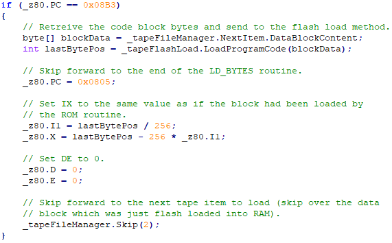
Controller class: Intercept the LD_PROG_1 routine and call the flash load method.
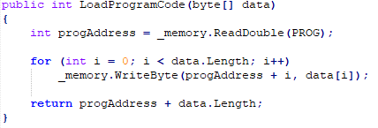
Flash Loader class: Load the program data block into RAM and report back the end address.
There are still some tape files that don't load correctly, and this is something I will investigate. However, I don't think the problem in those cases is the Basic loader.
In a previous post I explained how I implemented a simple CRT TV screen effect using a HLSL shader created in the Shazzam Tool. Recently I've realised that I don't use this shader much, mostly because I feel that it is a bit too "aggressive" to my taste. I wanted a softer image and had seen some nice shaders in other emulators that I wanted to try implement.
Since I hadn't used Shazzam in a while and since then had bought a new PC, I needed to download the program again, but I found that the site shazzam-tool.com was broken. The latest version I know of is 1.4 and that is from 2012, so I suppose the author isn't maintaining the project anymore. After some googling I found an installation package at https://shazzam.software.informer.com so I could go ahead and create some new effects (at some point I guess I should learn to compile HLSL files myself). Note that you need .Net 3.5 to run Shazzam (you will get an error saying that the program cannot find csc.exe otherwise). For reference, here is my original CRT shader with a diagonal 3 x 3 matrix: 
Original diagonal matrix
What I did was basically that I extended the original shader so that the horisontal shift of the R/G/B pixels is optional. Also, I made the overspill amount configurable. Finally I removed some unnecessary stuff and simplified the code. With these changes I have much better control of the effect and I have implemented two variants in the emulator - a vertical 3 x 3 raster with increased overspill and a scanline effect with 100 % overspill.
Vertical raster with increased overspill

Scanlines
Here is the HLSL code (download):
// This shader creates a CRT-like matrix inspired by this article by Svyatoslav Cherkasov: // http://www.gamasutra.com/blogs/SvyatoslavCherkasov/20140531/218753/Shader_tutorial_CRT_emulation.php // // A pixel matrix is overlaid on the input image. Each pixel is assigned a color: red, green or blue // in a repeating pattern. // The color of a pixel is inherited directly from the red, green or blue color component of // the underlying input image. // // In addition, there is the following functionality: // 1. The R/G/B pixels can be shifted horizontally with each row so that we get a 3x3 matrix // like this: // R G B // B R G // G B R // 2. An "overspill" can be added to each pixel to get a brighter and softer image. // Normally, if we have for example a red input color, we would get a 100 % red pixel followed // by a 0 % green and a 0 % blue pixel. If we add some red to the green and blue pixels, // the overall brightness is increased and the colors will look more natural. // 3. To achieve a scanline effect, pixel rows are grouped in three, where the second and // third row in each group can have a lower brightness. // Sampler sampler2D TexSampler : register(S0); // TextureSize float2 TextureSize : register(C0); // Brightness factor for darker scanlines float1 BrightnessFactorRow2 : register(C1); float1 BrightnessFactorRow3 : register(C2); // Overspill from the primary colors. float1 Overspill : register(C3); // Diagonal or vertical raster. float1 Diagonal : register(C4); // Shader float4 main(float2 texCoord : TEXCOORD) : COLOR { // Scale to int texture size. Row and col are the current coordinates in the bitmap from // the upper left corner. int row = texCoord.y * TextureSize.y; int col = texCoord.x * TextureSize.x; // Pick up the color at the current position and add some brightness. float4 color = tex2D(TexSampler, texCoord) + 0.1f; float4 outColor = float4(0, 0, 0, 1); float4 multiplier = float4(0, 0, 0, 1); // Get the pixel position within a 3 x 3 matrix. int row_check = (int)row % 3; int col_check = (int)col % 3; // The pixel color is handled by setting a R/G/B multiplier vector. // First check if a diagonal raster should be implemted. if(Diagonal == 1) // Process the pixels, shifting the colors one step to the right for every row // within the 3 x 3 matrix. { if(row_check == col_check) {multiplier.r = 1; multiplier.g = Overspill;multiplier.b = Overspill;} else if ((row_check == 0 && col_check == 1) || (row_check == 1 && col_check == 2) || (row_check == 2 && col_check == 0)) {multiplier.g = 1; multiplier.b = Overspill;multiplier.r = Overspill;} else {multiplier.b = 1; multiplier.r = Overspill;multiplier.g = Overspill;} } else // For a vertical raster, process the pixels without shifting. { if (col_check == 0) { multiplier.r = 1; multiplier.g = Overspill;multiplier.b = Overspill; } else if (col_check == 1) { multiplier.g = 1; multiplier.b = Overspill;multiplier.r = Overspill; } else { multiplier.b = 1; multiplier.r = Overspill;multiplier.g = Overspill; } } // Add scanlines. if (row_check == 1) { // Make the second of the three rows a bit darker to simulate a scan line. multiplier = multiplier * BrightnessFactorRow2; } if (row_check == 2) { // Make the last of the three rows a bit darker to simulate a scan line. multiplier = multiplier * BrightnessFactorRow3; } // Apply the multiplier to set the final color. outColor = color * multiplier; // The Alpha channel needs to be restored to 1 after all operations. outColor.a = 1; return outColor; } Recently, the game developer Alessandro Grussu discovered that the soundtrack of his new game Sophia II sounded strange on my emulator - specifically that something was wrong with the mix. He kindly provided me with his original PT3 file, which I could open in Vortex Tracker to analyze. After some head scratching and failed remedies (patiently tested by Alessandro), I finally understood that the problem was related to how my emulator translated the AY volume setting to an audio signal amplitude. The AY signal, which is generated by the AYSignalGenerator class, can have an amplitude between 0 and 1. Since the AY signal is played back by the same audio provider as the beeper, the AY signal is limited to a maximum amplitude of 0.1 to achieve balance between the two audio sources. So basically the AY volume setting 0 to 15 needs to be translated to a signal amplitude of 0 to 0.1. I had implemented this in a linear way, so that each AY volume step increased the signal amplitude by 0.00667 (0.1/15). This actually worked out quite well, at least I thought so (maybe because it never crossed my mind that it would be otherwise). However, the Sophia II soundtrack is very dynamic, and with my linear model the dynamics were largely lost. I needed to increase the perceived difference between low and high volume levels, by increasing the signal amplitude exponentially with higher AY volume levels. The solution, based purely on trial and error, was to relate the signal amplitude to the AY volume setting raised to the power of 3 like this: 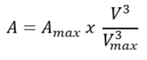 where: A is the signal amplitude (max value = 0.1) V is the AY volume setting (max value = 15) I'm not certain that the above relation is 100% correct, but the result sounds good to me. Update 2019-04-15: I found the correct function for the amplitude on the CPC Wiki, here. 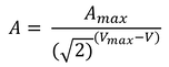 I also found this diagram in a manual for the AY-8910, which matches the function well: 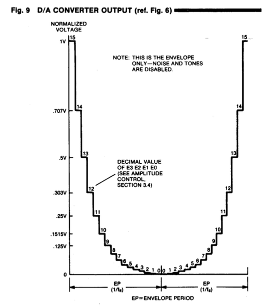 Update 2020-08-22:
I have replaced the above function with the actual, measured amplitude values reported here. As I described in a previous entry, the "floating bus" is an effect that occurs when an unattached port is read during display update, returning not the normal &FF, but instead the pixel- or attribute data which is currently being delivered to the CRT by the ULA. This effect was used in some games for the earlier Spectrum models to synchronize screen updates with the CRT beam position. When the Amstrad +2A/+3 models appeared on the scene it was understood that they did not have this effect, and programmers used other techniques to avoid flickering graphics. However, thanks to Cesar Hernandez, Ast A. Moore, Mark Woodmass and others it is now not only known that there actually is a floating bus effect on the +2A/+3 machines; the effect has also been described in detail. Suggested reading:
Emulation The floating bus effect on the +2A/+3 models works according to the following principle:
Many games have custom loaders which don't require headers for the code blocks, while still using some of the ROM tape loading routines. I have noticed that these loaders often bypass the LOAD A DATA BLOCK ROM routine at 0x0802 which the Controller class monitors (see Flash loader - Part 1), so for headerless loaders I choose to monitor 0x059F instead, which is a bit into the routine, just before the data block is actually loaded. When there is no header, the target address for the data is fetched from the IX register instead. Here is the Controller class code for handling headerless blocks: 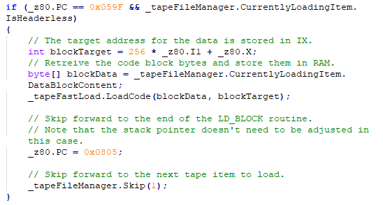 Most of the time, the regular loading process takes over when flash loading fails, but sometimes a file won't load correctly when flash loading is enabled. To make it easy to control this I added checkboxes for enabling flash load as well as speed load in the tape player window. 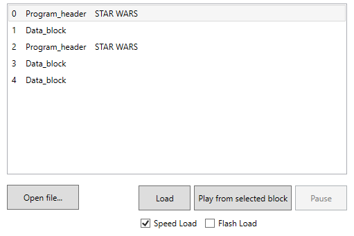 Having implemented flash load for code blocks (see Flash loader - part 1) I went ahead and looked into how to flash load a basic program. This is a bit more complex, since there are a number of system variables that need to be set correctly for the program to work. Aside from that, the process is the same as for code blocks, i.e. the Controller checks if the LD_BLOCK ROM routine is reached while a tape is playing. If the currently loading block is a program header, it will be flash loaded by a method in the Tape Flash Loader class, which looks like this: 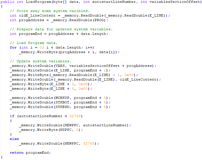 The method loads the data block to RAM, starting at the address found in the system variable PROG. It returns the end position of the program in RAM, which is used by the calling method to update the IX register. I'm not sure if all system variables are handled correctly but this seems to work. The best source of information about the system variables and how a program is mapped in memory that I could find was the Spectrum 128 Rom bank 0 disassembly by Matthew Wilson and others (full credits in the file). Here is a list of the system variables that I have identified (partly through trial-and-error) as important: 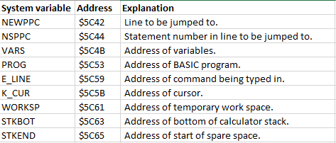 Normally, a Basic program is loaded by the "Load a data block" ROM routine (at 0x0802). This routine loads the header and then makes room for the Basic program before loading it into RAM.
The header gives the ROM routine information about the following:
The ROM routine sets the E_LINE variable to the first address after the end of the program space. The two bytes stored at this address needs to be preserved, so before E_LINE is updated, the bytes are copied from the previous address. Following the two bytes are a 0x0D byte and a 0x80 byte. Normally, the WORKSP, STKBOT and STKTOP variables seem to be set to the value of E_LINE + 2, so this is what I implemented (I tested this by breaking into the emulation at the end of the loading routine and checking the variables for a number of tape files). The VARS variable is set based on the header parameter and the PROG variable is preserved as it was before loading, as is the K_CUR variable. After the VARS area, a 0x80 byte is inserted. The ROM routine triggers autorun from the line number in the NEWPPC variable if it has a value < 32768. The autorun routine also needs a parameter for which statement number within the line it should start from. This is stored in NSPPC which must be set to 0. Update 2019-08-10: A few updates to the code and text descriptions were made. Later, this method was replaced by a more robust method which is described in this post. The nostalgic appeal of watching flickering border stripes while a Spectrum program is loading soon wears off, and almost every Spectrum emulator implements some technique to speed up the tape loading process (i.e. when loading TAP or TZX files). The most intuitive method of doing this is probably to just increase the emulation speed during tape loading, something I implemented in SoftSpectrum 48 early on. A more efficent but also more difficult method (at least if you want it to work on every type of tape file) is to bypass the translation of tape data to audio signals via the in port, and instead just load the data directly into RAM. This technique is sometimes called "flash load", and I will try to implement it to some degree in SoftSpectrum 48. The basic principle The basic principle behind flash load (as I understand it - which may be a simplification) is that you need to do do four things:
Of course, things become much more complicated when you have custom loaders which use only some or none of the ROM routines, but I will start with a simple solution where I just intercept the ROM routine for loading a code data block. Flash loading a code block The Controller class orchestrates everything that goes on in the emulator, so it will control the flash load function as well. To do this it needs to do the following things:
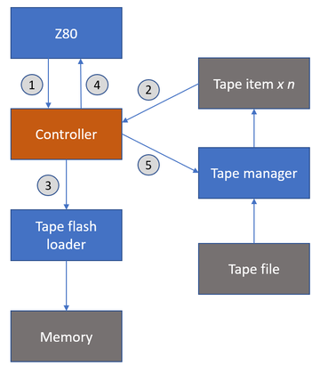 Below is the Controller code for handling Tape flash load as described above: 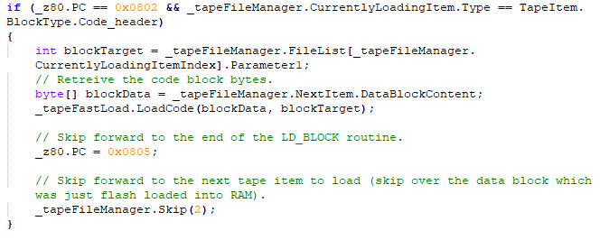 Apart from the new Controller code and the new Tape flash loader class (which only acts as an intermediary between the Controller and the Memory class), the other important change is that the Tape item class has been extended with a data array which holds the data block content. 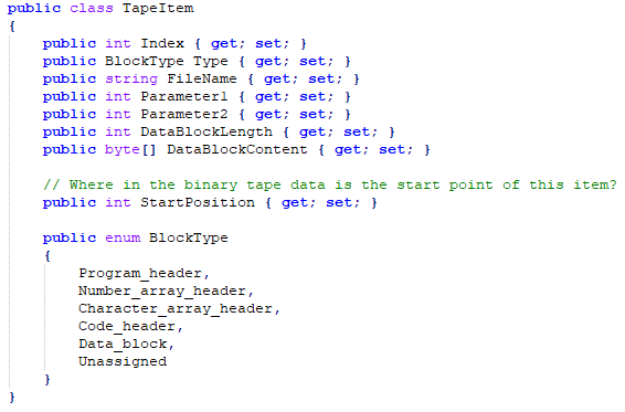 Previously, the Tape item class only held information about tape blocks to be presented in the tape player window. A tape item was created for each header block (by the Tape manager when opening a TAP or TZX file). Now, a tape item is created not only for headers but also for data blocks. What happens when the Controller detects a code header being loaded is that it retrieves the data array from the tape item following the header and copies this it to RAM. Result This first effort works surprisingly well, although the fact that program blocks are loaded in "real time" and that the code block flash load is not triggered until after the tape leader pulses have been processed (that is when the LD_BLOCK routine is activated) means that it still takes quite a while to load a tape. Also, headerless code blocks are not handled, so this will probably be the next step.
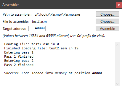
I'm not an assembly programmer myself, but sometimes I need to do minor stuff, mostly to test my emulator. For this I've been using different assemblers for PC/Windows (my favourite beeing Peter Hanratty's Z80 PC Assembler). This workflow is a bit impractical, so I've been considering building my own integrated assembler. Thinking about it I realized that it would be very difficult to make something on par with existing assemblers like Pasmo or Sjasm (not to mention building an efficient text editor), so I went for a simpler solution where I let the emulator call Pasmo to assemble a source file and then load the resulting code into RAM. This way I can achieve a fairly efficient workflow without having to reinvent the wheel (nevermind that my emulator is an example of doing just that ;-)). So, here is how it works:
 What is the floating bus? Ramsoft describes it in detail here, but in short it means that when the Z80 reads from an unattached port like 0xFF, the ULA returns the value 0xFF unless it is currently delivering data to the display, in which case this data is returned instead. When I first read about the floating bus, I found the task of emulating the effect a bit daunting, and not really worth the effort (only a few games use the effect). However, after I managed to time the Z80 execution to a virtual electron beam I decided to give the floating bus a shot. How to simulate the effect? The ULA fetches display data in repeated 8 T-state cycles. In these cycles, the first T-state is spent to collect a bitmap byte, the second T-State is spent to collect the corresponding attribute byte. Then the ULA moves on to collect the bitmap and attribute bytes for the next screen column. After this it waits 4 T-states until it repeats the cycle. The key to simulating this is then to have the Z80 timing in perfect order and to know if and where the ULA fetches screen data at the exact moment an unattached in port is read from. I already had the Z80 timing working, and the Sinclair FAQ Wiki describes which display position is read at which processor cycle, so what I had to do was to include the current T-state when the Z80 calls the In port. If the port in question is unattached, the following steps are performed:
It took some time to get this working, but I was rewarded by a very smooth-playing Sidewize (below). A game that uses the floating bus effect to ensure that the screen is updated after the CRT has traversed the game area. The author Steve Wetherill describes how he did this in a very interesting blog post. 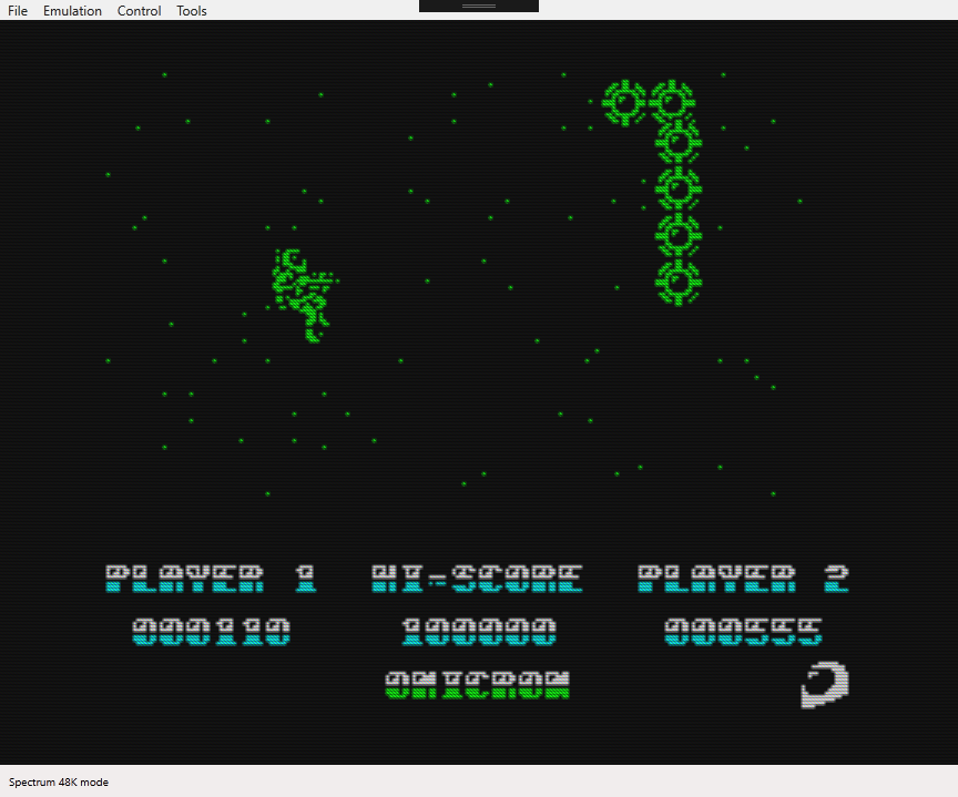 Sidewize, a game using the floating bus effect. Finally, a big step towards emulating the Spectrum 128 is finished. In a way it was easier than emulating the beeper, since the AY emulation can run on it's own in parallel with the CPU, whereas the beeper needs to be synced precisely with the processing time of each instruction. The AY emulation consists of three classes:
The figure below illustrates how the components interact.  As with the beeper, the NAudio library was used for emulating the AY chip. The audio output is handled by the AYController class, via WasapiOut. A mixer is used to handle input from the three AYChannel objects. For generating the square wave and white noise I initially used the SignalGenerator class included in the NAudio library. I then handled envelopes in the AYChannel class, where I used a timer to adjust the signal volume according to the selected envelope pattern. However, I realized that the envelopes can be very fast (kHz), which would require a precision that would be impossible with a timer. I therefore replaced the SignalGenerator with my own (well, to some extent anyway) class where I included envelopes integrated with the actual signal generation, which worked very well. I also had to modify the white noise algorithm to take into account the possibility to set the frequency of the white noise, which was not possible in the original SignalGenerator class.
History
The AY-3-8910 sound chip was introduced by General Instrument in the late seventies. The chip came in different variants and was used in many home computers during the eighties (Atari ST, Amstrad CPC and MSX among others). In 1985 Sinclair released the ZX Spectrum 128 which included the AY-3-8912 sound chip (a variant of AY-3-8910 with fewer pins) to complement the simple beeper used in previous models. General functions The sound chip has three channels, each with a square tone generator and a white noise generator. There is also a volume envelope function which can be applied to modify the signal's attack and decay (also in repeating patterns). Only one envelope can be applied at any time across all three channels but it can be switched on or off per channel. An important point is that the sound chip works like a state machine, meaning that if you set a parameter to a value, this parameter will stay the same until you change it. So, you can't tell the sound chip to produce a signal for a certain time period - you have to tell it exactly when to turn the signal on and off. Registers The AY-3-8910 sound chip has 14 registers for different parameters: Register Function Range 0 Channel A fine tone period 8-bit(0-255) 1 Channel A coarse tone period 4-bit(0-15) 2 Channel B fine tone period 8-bit(0-255) 3 Channel B coarse tone period 4-bit(0-15) 4 Channel C fine tone period 8-bit(0-255) 5 Channel C coarse tone period 4-bit(0-15) 6 Noise period 5-bit(0-31) 7 Mixer 8-bit 8 Channel A volume 4-bit(0-15) 9 Channel B volume 4-bit(0-15) 10 Channel C volume 4-bit(0-15) 11 Envelope fine period 8-bit(0-255) 12 Envelope coarse period 8-bit(0-255) 13 Envelope shape 4-bit(0-15)
Notes about the registers:
Value Shape
0-3:  \__________ (decay - silence)
4-7:  /|_________ (attack - silence)
8:    \|\|\|\|\|\ (repeated decay)
9:    \__________ (decay - silence)
10:   \/\/\/\/\/\ (repeated decay/attack)
11:   \|^^^^^    (decay - max volume)
12:   /|/|/|/|/|/ (repeated attack)
13:   /^^^^^      (attack - max volume)
14:   /\/\/\/\/\/ (repeated attack/decay)
15:   /|_________ (attack - silence)
How the Spectrum interacts with the sound chip
The Spectrum controls the sound chip registers by first placing the register number on port $FFFD and then placing the parameter value on port $BFFD. The AY-3-8912 sound chip emulation is now working, but I haven't fully integrated the code yet. In a coming post I will explain how the emulation is implemented. To illustrate the solution, I have put together a simple C# demo which can be downloaded here (source here). As with the beeper functions, it is based on the NAudio library, which has to be added to the source (available via NuGet). 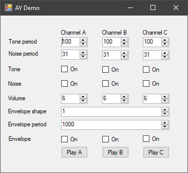 ZX Spectrum Tape Files The ZX Spectrum saves programs and data to tape in the form of audio recordings consisting of square wave signals with different wavelengths and durations. Here are some definitions:
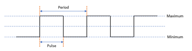 Tape data is encoded as two 855 T-state pulses for binary zero, and two 1,710 T-state pulses for binary one. A standard ZX Spectrum tape file consists of a header block and a data block. The header block being 19 bytes long (17 bytes plus a flag byte and a checksum byte) and contains the filename and the type of data block which follows (program, array, screen or bytes). For program data, the header can include a line number to start from for programs that shall execute automatically. To distinguish header blocks from data blocks, a sequence of leader pulses precedes each type of block. The leader pulse is 2,168 T-states long and is repeated 8,063 times for header blocks and 3,223 times for data blocks. After the leader pulses, two sync pulses (667 T-states plus 735 T-states long) follow to signal the beginning of the actual data. Read more about the tape file structure here. Custom tape routines can have other structures and encodings. Emulator Tape Files An emulator tape file contains all the necessary data for the emulator to recreate the audio pulses and input them to the emulator’s audio in port. Some emulators can bypass tape loading routines and instead convert the tape file data directly into emulated RAM, but this is not implemented in SoftSpectrum 48. The two most common tape file formats are:
SoftSpectrum 48 can load TAP files and most TZX files. Process The process for loading tape files in SoftSpectrum 48 is as follows:
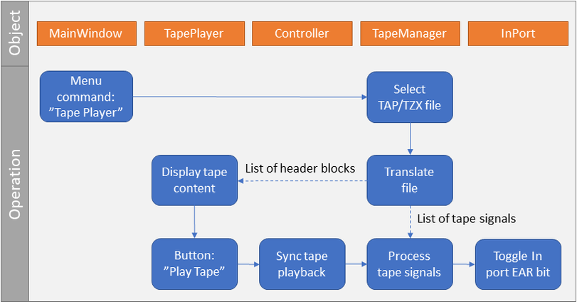 The tape loading process Speed Loading SoftSpectrum 48 uses a simple technique to increase the speed of the tape loading process. Whenever the CPU runs the instruction at 0x05C8, which is in the beginning of the ROM tape loading routines, CPU speed is increased to 400 %. Then, when the end of the tape file has been reached, speed is returned to its previous value.
2019-04-01: The table describing memory contention for Z80 instructions is replaced by a link to the FAQ Sinclair Wiki. Spectrum games are often easily recognizable by their garish colours and colour clashes. Or, when too much colour clash would have ruined the game (for example in isometric games like Knight Lore), monochrome game scenes. But there are games where apparently impossible colour effects are created, like in the examples below: The principle behind these effects is that the program keeps track of the exact position of the TV electron beam and updates the picture in perfect time so that the colour clash effect is negated. A good (and easy to understand) example of this is the full screen horizon in Aquaplane (see above). This effect can be achieved by keeping the border cyan-coloured until the beam reaches the end of a certain row and then change the border colour to blue. Again, when the beam starts over from the top left corner, the colour is changed back to cyan and so on. Of course, the same mechanism is behind the striped border appearing during tape loading, due to the fact that the border colour is updated with a high frequency to represent the data that is read from the tape.
To enable these kind of effects in an emulator, there are basically three things to handle:
The electron beam In the earliest incarnations of the emulator I updated the display once per interrupt frame, which worked fine for most games but of course not for the special effects described above. The optimal solution would be to update the screen bitmap one byte at a time at the exact same pace that the electron beam would sweep over the screen. Sadly, I haven't been able to do this yet without ruining the emulator's performance, but I can do one pixel row at a time with the correct pace. Update 2018-01-31: The screen is now updated one byte at at time in time with a simulated electron beam (not in debug mode yet though). Since the Z80 emulation in it self is much faster than a real Z80 processor, the emulation is done in "bursts" but paced so that the correct number of instructions are processed every 1/50:th. second. The length of each instruction is measured in processor periods - T States. The electron beam takes 224 T States to cover one screen row, so the principle is to trigger a screen row update every time enough instructions have been processed so that 224 T States have passed. The timings of the actual Spectrum screen update process is extensively covered by Chris Smith on his site www.zxdesign.info. The timing of the interrupt process The timing of the interrupt process is well known (in Interrupt mode 1, the process takes 13 T States and in mode 2 it takes 19 T States). The only thing needed here is to add these numbers to the number of T States processed by the Z80 so that the screen update process is triggered at the correct moment. The timings of the Z80 instructions The timings of the Z80 instructions are well documented so that is not a problem, but the Spectrum has a peculiarity which is essential to take into account if perfect timing is to be achieved. When the ULA (or the gate array in the +2A/3 models) reads display data from RAM to draw on the screen, the Z80 can't access the lower part of RAM 0x4000 - 0x7FFF, so the Z80 is paused every time a byte of screen data is read. This happens regularly at specific points during every frame and effectively slows down the Z80 somewhat. The effect is called memory contention and is explained in the FAQ Sinclair Wiki and at World of Spectrum along with a similar effect - I/O contention - which concerns read/write to I/O ports.
Updated 2019-03-31: The HLSL code now matches the examples.
The problem
Having worked for quite some time on getting the Z80 emulator to interpret even the most obscure instructions correctly I felt the need to do something a bit more "visible". I decided to have a go at implementing a CRT filter to make the display more realistic. This proved technically easier than I thought and even though the result is something of a compromise I think it looks quite good. Before LCD, plasma and other flat screen digital display technologies, TV:s and monitors where built on cathode ray tube technology, which made them bulky, heavy and energy inefficient. Modern flat screen displays are superior in many ways, but because of their higher resolution and their digital precision, they produce a very different result compared to that of an old TV. Rendering a Sinclair Spectrum screen in native resolution (254 x 192 pixels plus border) on a modern display results in a very small and crystal clear image like this: 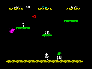
Spectrum screen in native resolution.
If we scale up the image four times, to get the size about right, we get this very blocky image with sharp edges:

Magnified Spectrum screen on a LCD display.
This is a result you would never get on a CRT TV, where the image instead would be slightly blurred with a visible raster of red, green and blue glowing dots. The dots where phosphors which emitted light of a specific color when hit by the electron beam from the cathode ray tube, which swept over the screen in a horizontal pattern. There could also be more or less visible scan lines (darker lines between the lines where the electron beam hit the phospors). Below is a close-up picture of a CRT display, which illustrates how the individual pixels of the displayed image are blurred by the analog nature of the CRT technique.
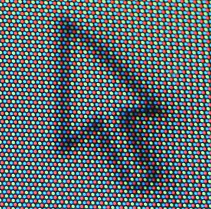
Magnified picture of a CRT display.
The solution
How then to recreate something like a CRT image on a modern display? First of all, there is a built in function i WPF to control how an image is scaled up. There are basically two modes:
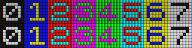
I have used this effect (linear scaling) in SoftSpectrum 48 since the beginning, and it is available in the Emulation menu as "Anti-alias (on/off)".
However, I wanted to recreate the impression of slightly visible phosphors and scanlines as well and soon realized that I would need to use the GPU do this. In WPF, this can be done using what is called a Pixel shader effect. What it does is that it applies a HLSL shader to any GUI object. A shader is a program which is is processed by the GPU to apply an effect (color, distortion etc. to an image) and HLSL is the GPU programming language for DirectX. I had never worked with HLSL or shaders at all before, but I found Shazzam, which is an excellent editor and learning tool for HLSL programming. I built, tested and compiled my shader in Shazzam, which also generated the necessary C# class to encapsulate the compiled shader in the emulator. For the actual implementation of the CRT filter I found this article by Svyatoslav Cherkasov very helpful. I started experimenting with different algorithms to replace every Spectrum pixel with a number of red, green and blue pixels. I worked with a 300% enlarged image so that I had 9 screen pixels for every Spectrum pixel. My first attempt looked like this (unprocessed image to the left):
Magnified, the red, green and blue pixels are clearly visible:
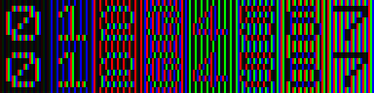
Magnified image of 3x3 raster
However, as Svyatoslav Cherkasov noted in his article, this algorithm results in a too dark result. The solution is to let some of the color "spill over" to adjacent pixels. That is, if we have a 100 % red Spectrum pixel, the red pixel will obviously be 100 % red, but we also add a smaller percentage red to the green and blue pixels. Here is an example of what happens then:

Color "over spill"
To add scan-lines I simply made every third row sligtly darker, like this:
Scan lines
I found the "square" pattern a bit too apparent so I tried to shift the pixels one step to the right for every row, with this result:

Shifted pixels
As a final touch, I applied the anti-alias effect:

Anti-alias
I find the result quite OK, perhaps because I haven't been near a CRT display for some time (let alone one connected to a real Spectrum), but considering how little effort it took to do this I'm happy.
Here is the final HLSL-code: // This shader creates a CRT-like matrix inspired by this article by Svyatoslav Cherkasov: // http://www.gamasutra.com/blogs/SvyatoslavCherkasov/20140531/218753/Shader_tutorial_CRT_emulation.php // The matrix consists of repeated RGB-pixels with a some "overspill" so that if we have a 100 % red bitmap pixel // the adjacent green and blue pixels will also have some red color added, which makes the image brighter and softer. // Also, the RGB pattern is shifted to the right one pixel for every row to give a somewhat less blocky effect. // A scan-line effect is achieved by making every third row darker. // Sampler sampler2D TexSampler: register(S0); // TextureSize float2 TextureSize: register(C0); // Factor for dark scanlines float1 FactorDark: register(C1); // Brightness float Brightness: register(C2); // Shader float4 main(float2 texCoord: TEXCOORD): COLOR { // Scale to int texture size. Row and col are // the current coordinates in the bitmap from // the upper left corner. int row = texCoord.y * TextureSize.y; int col = texCoord.x * TextureSize.x; // Pick up the color at the current position. // Add 0.1 to make black areas dark grey. float4 color = tex2D(TexSampler, texCoord) + 0.1 f; // Set two variables for overspill from the primary colors to the other colors. float spillOver1 = 0.7; float spillOver2 = 0.5; float4 outColor = float4(0, 0, 0, 1); float4 multiplier = float4(0, 0, 0, 1); float4 darkLine = float4(1, 1, 1, 1) * FactorDark; // Set the colors of the "red", "green" and "blue" pixels, // with spill over from adjacent pixels. // Process tree rows of three pixels and shift the colors // one step to the right for every row. int row_check = (int) row % 3; if (row_check == 0) { int col_check = (int) col % 3; if (col_check == 0) { multiplier.r = 1; multiplier.g = spillOver1; multiplier.b = spillOver2; } else if (col_check == 1) { multiplier.g = 1; multiplier.b = spillOver1; multiplier.r = spillOver2; } else { multiplier.b = 1; multiplier.r = spillOver1; multiplier.g = spillOver2; } } if (row_check == 1) { int col_check = (int) col % 3; if (col_check == 1) { multiplier.r = 1; multiplier.g = spillOver1; multiplier.b = spillOver2; } else if (col_check == 2) { multiplier.g = 1; multiplier.b = spillOver1; multiplier.r = spillOver2; } else { multiplier.b = 1; multiplier.r = spillOver1; multiplier.g = spillOver2; } } if (row_check == 2) { int col_check = (int) col % 3; if (col_check == 2) { multiplier.r = 1; multiplier.g = spillOver1; multiplier.b = spillOver2; } else if (col_check == 0) { multiplier.g = 1; multiplier.b = spillOver1; multiplier.r = spillOver2; } else { multiplier.b = 1; multiplier.r = spillOver1; multiplier.g = spillOver2; } // Make the last of the three rows a bit darker to simulate a scan line. multiplier = multiplier * darkLine; } outColor = color * multiplier; // Apply brightness. outColor = outColor * Brightness; // The Alpha channel needs to be restored to one after all operations. outColor.a = 1; return outColor; } I have been a bit sloppy with the R register, which has led to some strange emulation problems in games like Green Beret where the R register is frequently used. The R register should be incremented once for every instruction, with some additional rules and conditions. For example, prefixed instructions like CB-02 (RLC D) causes R to be incremented twice. Furthermore, only bit 0-6 are incremented, while bit 7 remains untouched. For a complete description of these rules and conditions, see http://www.z80.info.
One of my mistakes was that I treated bit 7 as completely static - I forgot that there are instructions to set R to any value 0-255. Now the code for incrementing R looks like this: R = (R & 128) | (R + 1) & 127; The R-register can be used either as a counter, like in Green Beret where it controls the timing of some sound effects, or as a way to get some sort of random number triggered by user input at a random certain point in time. |
Archives
November 2020
Categories
All
|


 RSS Feed
