|
I thought I had all timings reasonably under control, but this was not the case. The 128 KB Spectrum models can switch between the normal screen memory (bank 5) and the shadow screen (bank 7) by writing to port #7FFD. This feature can be seen used in demos like this. I had assumed that the actual bank switch would happen instantaneously after the command was received and the correct amount of T-states had passed, but things turned out to be a bit more complicated. There is a suite of test programs zxtests-3 written by Jan Bobrowski which used to be published at http://wizard.ae.krakow.pl/~jb/qaop/tests.html. This site is not online anymore but it can be accessed on waybackmachine.org. These tests are very useful for testing emulation of various timing aspects and they have also sometimes been adapted by developers to examine specific scenarios. In 2014, Patrik Rak did some modifications to the test suite and added a test ptime which examines what happens when the screen memory is switched at different T-states. This is discussed on the World of Spectrum forum here and here. What the ptime test does is that it triggers a screen bank switch at a specific T-state which can be increased or decreased manually. Before the switch, a black screen in bank 7 is displayed, which then switches to this screen in bank 5: 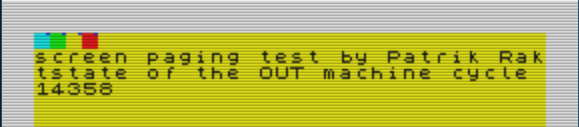 The ptime test. As the T-state at which the switch is triggered is increased, a black line from the shadow screen will appear. This is because the switch occurs after the ULA has already begun drawing the screen from the black shadow screen data. 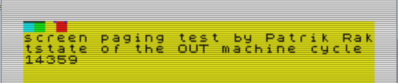 The ptime test with a visible black line. I don't have access to any 128 KB machine, but test results from a Spectrum 128 and a +3 were reported in one of the World of Spectrum forum threads and my emulator gave different results.
Generally, to achieve correct timings for the screen, an emulator needs to handle all the Z80 timings exactly correct including effects from memory- and IO-contention. Then, the ULA 8 T-state screen update cycle needs to be simulated (this is the cycle where the ULA fetches pixel and attribute data and the writes the video byte to the screen). Also, there is the timing for when the screen updates begin in a new frame and the time between pixel rows. My emulator had passed all the tests I had come across regarding screen timings so my theory was that the problem concerned the screen memory bank switch specifically . Since my emulator displayed the black line at an earlier point than what was reported for real machines I assumed that there must be a short delay after the OUT command to port #7FFD until the switch occurred. After some experimenting I found that a 3 T-state delay resulted in correct results for Spectrum 128 emulation but I couldn't find a working delay value for the +2A/+3 emulation. It turned out that the solution was to rearrange the screen update cycle slightly for these machines (which have their own version of the ULA) and then add a 2 T-state delay before the screen bank switch. An interesting thing about the update cycle is that in the WOS thread there are two different accounts of how the ptime test behaves on +3 machines. They agree regarding the pattern for the black line, but one report says that the blue pixel in the colored squares disappears just before the line enters the square, while the other report says that the blue pixel remains until it is overwritten by the black line. I noticed that if I let the emulator fetch the attribute byte one T-state after the pixel byte, the blue pixel disappeared as described in one of the reports but then the Megashock demo was broken, so put the pixel and attribute byte fetch in the same T-state. So, now my emulator behaves as reported on the World of Spectrum forum thread (with reservation for the disappearing blue pixels reported by one user). Update 2019-10-02: I found this thread on the World of Spectrum Forums where a similar test (ptime-128) is published, and I was directed by the author to this thread where there are more test reports for the test. SoftSpectrum 48 did in most cases not behave as the tested hardware so I will have to examine this topic further. Update 2019-10-06: The ptime-128 test now works correctly (according the the test results in the WOS threads) for uncontended IO ports, so the +2A/+3 emulation is OK since they don't have any IO contention, but the Sinclair 128K emulation is not correct when contended ports are used. I will get back to this topic to see what can be done.
0 Comments
2019-04-01: The table describing memory contention for Z80 instructions is replaced by a link to the FAQ Sinclair Wiki. Spectrum games are often easily recognizable by their garish colours and colour clashes. Or, when too much colour clash would have ruined the game (for example in isometric games like Knight Lore), monochrome game scenes. But there are games where apparently impossible colour effects are created, like in the examples below: The principle behind these effects is that the program keeps track of the exact position of the TV electron beam and updates the picture in perfect time so that the colour clash effect is negated. A good (and easy to understand) example of this is the full screen horizon in Aquaplane (see above). This effect can be achieved by keeping the border cyan-coloured until the beam reaches the end of a certain row and then change the border colour to blue. Again, when the beam starts over from the top left corner, the colour is changed back to cyan and so on. Of course, the same mechanism is behind the striped border appearing during tape loading, due to the fact that the border colour is updated with a high frequency to represent the data that is read from the tape.
To enable these kind of effects in an emulator, there are basically three things to handle:
The electron beam In the earliest incarnations of the emulator I updated the display once per interrupt frame, which worked fine for most games but of course not for the special effects described above. The optimal solution would be to update the screen bitmap one byte at a time at the exact same pace that the electron beam would sweep over the screen. Sadly, I haven't been able to do this yet without ruining the emulator's performance, but I can do one pixel row at a time with the correct pace. Update 2018-01-31: The screen is now updated one byte at at time in time with a simulated electron beam (not in debug mode yet though). Since the Z80 emulation in it self is much faster than a real Z80 processor, the emulation is done in "bursts" but paced so that the correct number of instructions are processed every 1/50:th. second. The length of each instruction is measured in processor periods - T States. The electron beam takes 224 T States to cover one screen row, so the principle is to trigger a screen row update every time enough instructions have been processed so that 224 T States have passed. The timings of the actual Spectrum screen update process is extensively covered by Chris Smith on his site www.zxdesign.info. The timing of the interrupt process The timing of the interrupt process is well known (in Interrupt mode 1, the process takes 13 T States and in mode 2 it takes 19 T States). The only thing needed here is to add these numbers to the number of T States processed by the Z80 so that the screen update process is triggered at the correct moment. The timings of the Z80 instructions The timings of the Z80 instructions are well documented so that is not a problem, but the Spectrum has a peculiarity which is essential to take into account if perfect timing is to be achieved. When the ULA (or the gate array in the +2A/3 models) reads display data from RAM to draw on the screen, the Z80 can't access the lower part of RAM 0x4000 - 0x7FFF, so the Z80 is paused every time a byte of screen data is read. This happens regularly at specific points during every frame and effectively slows down the Z80 somewhat. The effect is called memory contention and is explained in the FAQ Sinclair Wiki and at World of Spectrum along with a similar effect - I/O contention - which concerns read/write to I/O ports. |
Archives
November 2020
Categories
All
|
 RSS Feed
