|
In a previous post I explained how I implemented a simple CRT TV screen effect using a HLSL shader created in the Shazzam Tool. Recently I've realised that I don't use this shader much, mostly because I feel that it is a bit too "aggressive" to my taste. I wanted a softer image and had seen some nice shaders in other emulators that I wanted to try implement.
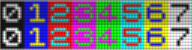
Since I hadn't used Shazzam in a while and since then had bought a new PC, I needed to download the program again, but I found that the site shazzam-tool.com was broken. The latest version I know of is 1.4 and that is from 2012, so I suppose the author isn't maintaining the project anymore. After some googling I found an installation package at https://shazzam.software.informer.com so I could go ahead and create some new effects (at some point I guess I should learn to compile HLSL files myself). Note that you need .Net 3.5 to run Shazzam (you will get an error saying that the program cannot find csc.exe otherwise). For reference, here is my original CRT shader with a diagonal 3 x 3 matrix: 
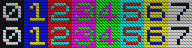
Original diagonal matrix
What I did was basically that I extended the original shader so that the horisontal shift of the R/G/B pixels is optional. Also, I made the overspill amount configurable. Finally I removed some unnecessary stuff and simplified the code. With these changes I have much better control of the effect and I have implemented two variants in the emulator - a vertical 3 x 3 raster with increased overspill and a scanline effect with 100 % overspill.
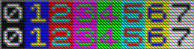
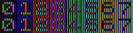
Vertical raster with increased overspill
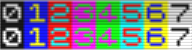
Scanlines
Here is the HLSL code (download):
// This shader creates a CRT-like matrix inspired by this article by Svyatoslav Cherkasov:
// http://www.gamasutra.com/blogs/SvyatoslavCherkasov/20140531/218753/Shader_tutorial_CRT_emulation.php
//
// A pixel matrix is overlaid on the input image. Each pixel is assigned a color: red, green or blue
// in a repeating pattern.
// The color of a pixel is inherited directly from the red, green or blue color component of
// the underlying input image.
//
// In addition, there is the following functionality:
// 1. The R/G/B pixels can be shifted horizontally with each row so that we get a 3x3 matrix
//     like this:
//     R G B
//     B R G
//     G B R
// 2. An "overspill" can be added to each pixel to get a brighter and softer image.
//    Normally, if we have for example a red input color, we would get a 100 % red pixel followed
//    by a 0 % green and a 0 % blue pixel. If we add some red to the green and blue pixels,
//    the overall brightness is increased and the colors will look more natural.
// 3. To achieve a scanline effect, pixel rows are grouped in three, where the second and
//    third row in each group can have a lower brightness.

// Sampler
sampler2D TexSampler : register(S0);

// TextureSize
float2 TextureSize : register(C0);

// Brightness factor for darker scanlines
float1 BrightnessFactorRow2 : register(C1);
float1 BrightnessFactorRow3 : register(C2);

// Overspill from the primary colors.
float1 Overspill : register(C3);

// Diagonal or vertical raster.
float1 Diagonal : register(C4);

// Shader
float4 main(float2 texCoord : TEXCOORD) : COLOR
{
        // Scale to int texture size. Row and col are the current coordinates in the bitmap from
        // the upper left corner.
        int row = texCoord.y * TextureSize.y;
        int col = texCoord.x * TextureSize.x;

        // Pick up the color at the current position and add some brightness.
        float4 color = tex2D(TexSampler, texCoord) + 0.1f;

        float4 outColor = float4(0, 0, 0, 1);
        float4 multiplier = float4(0, 0, 0, 1);

        // Get the pixel position within a 3 x 3 matrix.
        int row_check = (int)row % 3;
        int col_check = (int)col % 3;

        // The pixel color is handled by setting a R/G/B multiplier vector.
        // First check if a diagonal raster should be implemted.
        if(Diagonal == 1)
                // Process the pixels, shifting the colors one step to the right for every row
                // within the 3 x 3 matrix.
    {
        if(row_check == col_check)
                {multiplier.r = 1; multiplier.g = Overspill;multiplier.b = Overspill;}
                else if ((row_check == 0 && col_check == 1) || (row_check == 1 && col_check == 2) || (row_check == 2 && col_check == 0))
                {multiplier.g = 1; multiplier.b = Overspill;multiplier.r = Overspill;}
                else
                {multiplier.b = 1; multiplier.r = Overspill;multiplier.g = Overspill;}
    }
    else
    // For a vertical raster, process the pixels without shifting.
    {
    if (col_check == 0)
                        {
                                multiplier.r = 1; multiplier.g = Overspill;multiplier.b = Overspill;
                        }
                else if (col_check == 1)
                {
                        multiplier.g = 1; multiplier.b = Overspill;multiplier.r = Overspill;
                }
                else
                {
                        multiplier.b = 1; multiplier.r = Overspill;multiplier.g = Overspill;
                }
    }

        // Add scanlines.
        if (row_check == 1)
                {
                // Make the second of the three rows a bit darker to simulate a scan line.
                multiplier = multiplier * BrightnessFactorRow2;
                }

        if (row_check == 2)
                {
                // Make the last of the three rows a bit darker to simulate a scan line.
                multiplier = multiplier * BrightnessFactorRow3;
                }

        // Apply the multiplier to set the final color.
        outColor = color * multiplier;

        // The Alpha channel needs to be restored to 1 after all operations.
        outColor.a = 1;

        return outColor;
}
0 Comments
Updated 2019-03-31: The HLSL code now matches the examples.
The problem
Having worked for quite some time on getting the Z80 emulator to interpret even the most obscure instructions correctly I felt the need to do something a bit more "visible". I decided to have a go at implementing a CRT filter to make the display more realistic. This proved technically easier than I thought and even though the result is something of a compromise I think it looks quite good. Before LCD, plasma and other flat screen digital display technologies, TV:s and monitors where built on cathode ray tube technology, which made them bulky, heavy and energy inefficient. Modern flat screen displays are superior in many ways, but because of their higher resolution and their digital precision, they produce a very different result compared to that of an old TV. Rendering a Sinclair Spectrum screen in native resolution (254 x 192 pixels plus border) on a modern display results in a very small and crystal clear image like this: 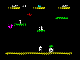
Spectrum screen in native resolution.
If we scale up the image four times, to get the size about right, we get this very blocky image with sharp edges:
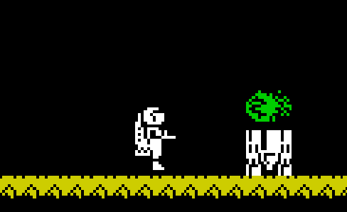
Magnified Spectrum screen on a LCD display.
This is a result you would never get on a CRT TV, where the image instead would be slightly blurred with a visible raster of red, green and blue glowing dots. The dots where phosphors which emitted light of a specific color when hit by the electron beam from the cathode ray tube, which swept over the screen in a horizontal pattern. There could also be more or less visible scan lines (darker lines between the lines where the electron beam hit the phospors). Below is a close-up picture of a CRT display, which illustrates how the individual pixels of the displayed image are blurred by the analog nature of the CRT technique.
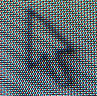
Magnified picture of a CRT display.
The solution
How then to recreate something like a CRT image on a modern display? First of all, there is a built in function i WPF to control how an image is scaled up. There are basically two modes:
I have used this effect (linear scaling) in SoftSpectrum 48 since the beginning, and it is available in the Emulation menu as "Anti-alias (on/off)".
However, I wanted to recreate the impression of slightly visible phosphors and scanlines as well and soon realized that I would need to use the GPU do this. In WPF, this can be done using what is called a Pixel shader effect. What it does is that it applies a HLSL shader to any GUI object. A shader is a program which is is processed by the GPU to apply an effect (color, distortion etc. to an image) and HLSL is the GPU programming language for DirectX. I had never worked with HLSL or shaders at all before, but I found Shazzam, which is an excellent editor and learning tool for HLSL programming. I built, tested and compiled my shader in Shazzam, which also generated the necessary C# class to encapsulate the compiled shader in the emulator. For the actual implementation of the CRT filter I found this article by Svyatoslav Cherkasov very helpful. I started experimenting with different algorithms to replace every Spectrum pixel with a number of red, green and blue pixels. I worked with a 300% enlarged image so that I had 9 screen pixels for every Spectrum pixel. My first attempt looked like this (unprocessed image to the left):
Magnified, the red, green and blue pixels are clearly visible:
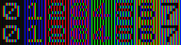
Magnified image of 3x3 raster
However, as Svyatoslav Cherkasov noted in his article, this algorithm results in a too dark result. The solution is to let some of the color "spill over" to adjacent pixels. That is, if we have a 100 % red Spectrum pixel, the red pixel will obviously be 100 % red, but we also add a smaller percentage red to the green and blue pixels. Here is an example of what happens then:
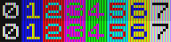
Color "over spill"
To add scan-lines I simply made every third row sligtly darker, like this:
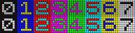
Scan lines
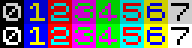
I found the "square" pattern a bit too apparent so I tried to shift the pixels one step to the right for every row, with this result:
Shifted pixels
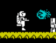
As a final touch, I applied the anti-alias effect:
Anti-alias
I find the result quite OK, perhaps because I haven't been near a CRT display for some time (let alone one connected to a real Spectrum), but considering how little effort it took to do this I'm happy.
Here is the final HLSL-code: // This shader creates a CRT-like matrix inspired by this article by Svyatoslav Cherkasov: // http://www.gamasutra.com/blogs/SvyatoslavCherkasov/20140531/218753/Shader_tutorial_CRT_emulation.php // The matrix consists of repeated RGB-pixels with a some "overspill" so that if we have a 100 % red bitmap pixel // the adjacent green and blue pixels will also have some red color added, which makes the image brighter and softer. // Also, the RGB pattern is shifted to the right one pixel for every row to give a somewhat less blocky effect. // A scan-line effect is achieved by making every third row darker. // Sampler sampler2D TexSampler: register(S0); // TextureSize float2 TextureSize: register(C0); // Factor for dark scanlines float1 FactorDark: register(C1); // Brightness float Brightness: register(C2); // Shader float4 main(float2 texCoord: TEXCOORD): COLOR { // Scale to int texture size. Row and col are // the current coordinates in the bitmap from // the upper left corner. int row = texCoord.y * TextureSize.y; int col = texCoord.x * TextureSize.x; // Pick up the color at the current position. // Add 0.1 to make black areas dark grey. float4 color = tex2D(TexSampler, texCoord) + 0.1 f; // Set two variables for overspill from the primary colors to the other colors. float spillOver1 = 0.7; float spillOver2 = 0.5; float4 outColor = float4(0, 0, 0, 1); float4 multiplier = float4(0, 0, 0, 1); float4 darkLine = float4(1, 1, 1, 1) * FactorDark; // Set the colors of the "red", "green" and "blue" pixels, // with spill over from adjacent pixels. // Process tree rows of three pixels and shift the colors // one step to the right for every row. int row_check = (int) row % 3; if (row_check == 0) { int col_check = (int) col % 3; if (col_check == 0) { multiplier.r = 1; multiplier.g = spillOver1; multiplier.b = spillOver2; } else if (col_check == 1) { multiplier.g = 1; multiplier.b = spillOver1; multiplier.r = spillOver2; } else { multiplier.b = 1; multiplier.r = spillOver1; multiplier.g = spillOver2; } } if (row_check == 1) { int col_check = (int) col % 3; if (col_check == 1) { multiplier.r = 1; multiplier.g = spillOver1; multiplier.b = spillOver2; } else if (col_check == 2) { multiplier.g = 1; multiplier.b = spillOver1; multiplier.r = spillOver2; } else { multiplier.b = 1; multiplier.r = spillOver1; multiplier.g = spillOver2; } } if (row_check == 2) { int col_check = (int) col % 3; if (col_check == 2) { multiplier.r = 1; multiplier.g = spillOver1; multiplier.b = spillOver2; } else if (col_check == 0) { multiplier.g = 1; multiplier.b = spillOver1; multiplier.r = spillOver2; } else { multiplier.b = 1; multiplier.r = spillOver1; multiplier.g = spillOver2; } // Make the last of the three rows a bit darker to simulate a scan line. multiplier = multiplier * darkLine; } outColor = color * multiplier; // Apply brightness. outColor = outColor * Brightness; // The Alpha channel needs to be restored to one after all operations. outColor.a = 1; return outColor; } |
Archives
November 2020
Categories
All
|

 RSS Feed
